Db9 Pinout Bose Wiring Diagram
SoundTouch 130 44 out of 5 stars 206 1395 13. RS232 Pinout Below is the pinout of a typical standard male 9-pin RS232 connector this connector type is also referred to as a DB9 connector.
Rs232 connector pin assignment plc cable information lammert bies transmit 15 vga diagram full db15 to rj45 wiring 2000 the standard null modem pinout db9 crossover attwiki jamma nation x multiple kick harnesses pri avaya ip office tek tips advanced serial debugging guide residential db25 qrz forums for duet breakout box pinouts low voltage cables.

Db9 pinout bose wiring diagram. Pinout and signals for building a serial RS232 nullmodem cable. According to Usb To Db9 Wiring Diagram there are just four wires used from the cable. HQRP 9-pin Male to 9-pin Male MM Audio Input Cable Compatible with Bose 302580-1001 Replacement Lifestyle 135 235 48 T10 V20.
GM 2003-2007 BOSE Amplifier pinout. Pinout of PC serial port RS-232 DE9 and layout of 9 pin D-SUB male connector and 10 pin IDC male connectorThis RS232C DE-9 usually miscalled DB-9 port is available in some PCs and many other devices. Communication over this port is always at 38400 baud with eight 8 data bits no parity and one 1 stop bit.
Architectural wiring diagrams act out the approximate locations and interconnections of receptacles lighting and long-lasting electrical services in a building. Typically it utilizes black green red and white cable colours. 24 pin GMC Radio Head Unit 12110088 connector.
Wiring diagram bose surround wiring schematic diagram 11. Need pinouts for mini-DIN 9-pin Bose Link to RJ45 cable AND pinouts for mini-DIN 9-pin Bose Link to RCA plug. Pinout and wiring layout for many situations.
In accordance with Modem Usb To Db9 Wiring Diagram there are just four wires used inside the cable. Rs232 serial null modem cable wiring crossover or vs straight pinout to usb diagram and should i use cables box db9 tri rs 232 connections that work sealevel information port 18663 9 pin male direct connection rj45 configuration female adapter 449 solstice x 25 yost device on 422 aston martin full advanced debugging. A wiring diagram is a simplified standard pictorial depiction of an electrical circuit.
Diagram rj45 db9 cisco console cable wiring full version hd quality chevydiagrams virtual edge it technical note serial pinouts for access to fortinet hardware products female seniorsclub circuit joint plus haus yost device rs232 on lammert bies wires youth hazzart honda prelude harness schematics field ethernet 2003 cavalier subaruoutback tukune jeanjaures37 fr Diagram Rj45 Db9 Cisco Console. Use this cable between two DTE Data Terminal Equipment devices for instance two computers. The red one is for positive wire with DC ability of 5 liter.
The RMC100 CPU module has a DTE DB9 serial port labeled RS-232 Monitor Both RMCWin and the RMCLink ActiveX Control and NET Assembly Component use this port. Interconnecting wire routes may be shown approximately where particular receptacles or fixtures must be on a common circuit. Db9 Null Modem Wiring Diagram Tri State Belimo Actuator Bedebis Waystar Fr.
Black wire serves as ground just like in every other apparatus. Generally Pin 1 is marked on the front of the connector right next to the pin - though you may need a. Null modem cable DB9-DB9.
DB9 to DB25 conversion and null modem wiring diagrams. Using the CPU 9-pin Serial Port. An RS-232 serial port was once a standard feature of a personal computer used for connections to modems printers mice data storage uninterruptible power supplies and other peripheral.
The red one is for positive cable with DC power of 5 volts. It shows the components of the circuit as simplified shapes and also the power as well as signal connections in between the devices. Pinouts Devices Connectors.
The wiring diagram isDB9 and DB25 Male and Female Pin Numbering These diagrams show the male grey background and female black background pin numbering for DB9 and DB25 sub-miniature connectors. Black cable serves as ground just like in every other apparatus. Pinout of GMC 2003-2007 BOSE Amplifierpn 15199884 15191601 15199992 15114454.
25 pin D-SUB male photo and diagram Calcomp Drawingboard 3 DB25 F w 12V to 8 pin DIN mini pinout and wiring Centronics to LapLink adapter pinoutFigure 2 is the wiring scheme for the plug side of an RJ connector in accordance with TB standards. Pinouts Genuine GM Opel Chevrolet Buick Pontiac Saturn Cadillac car audio. A computers serial COM port DTE is usually a male port as shown below and any peripheral devices you connect to this port usually has a female connector DCE.
Typically it utilizes black green white and red wire colors. Found an old Bose Lifestyle 18 DVD headunit a PS18 LSPS amplified subwoofer AND an Acoustimass 10 passive sub but have no cables. Genuine radio stereo harness pin assignment.
Diagram Pinoutguide Micro Usb Wiring Diagram blogging zipmail com br db9 pinout diagram haldex ecu pinout haledex ecu pin out howto wire dsub9 to usb type c chargerwiring. Appendix A Rs232 And Control Port Wiring. Assortment of bose amp wiring diagram.
 Cat 6 Wiring Diagram Rj45 Emejing Ethernet Cable Wire Gallery Striking Network To Cat6 Ethernet Cable Ethernet Wiring Rj45
 Voltage Conversion In Pc Serial Db9 Port Electrical Engineering Stack Exchange
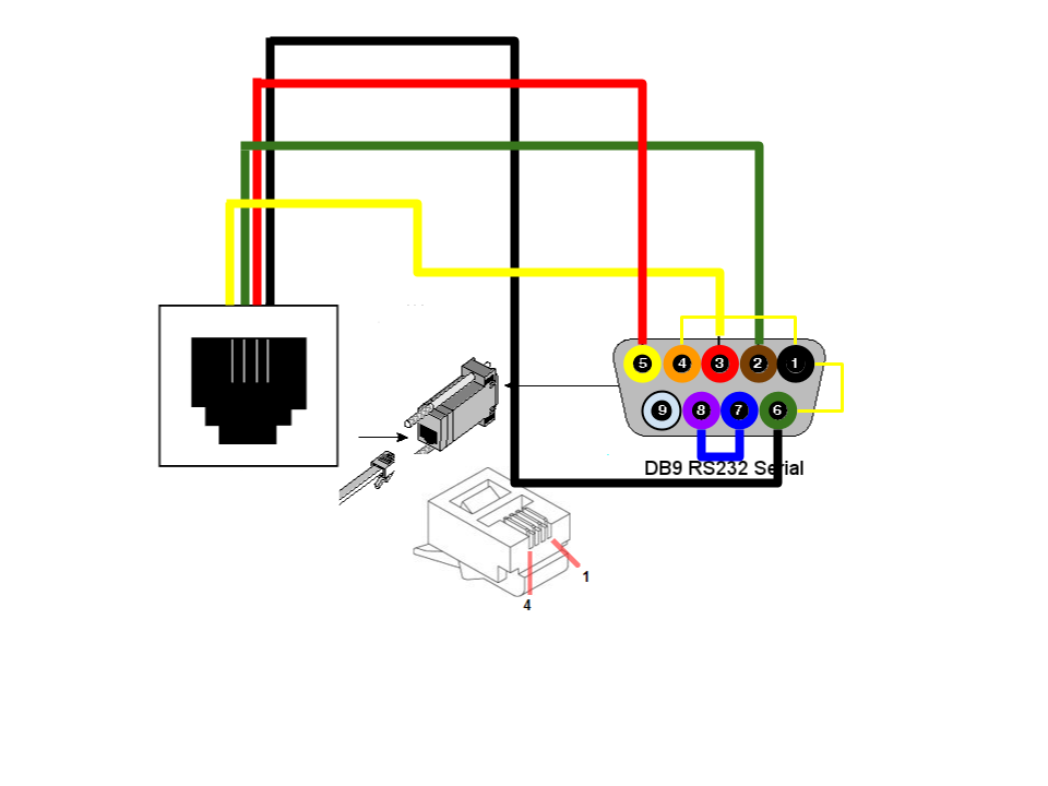
 Wiring Diagram Rj45 To Db9 Serial Port Usb Pinout Inside Diagrams Throughout Serial Port Usb Usb Cable
 Rj12 To Rs232 Serial Port How To Make Notes Circuit Diagram
Diagram Db9 Pinout Bose Wiring Diagram Full Version Hd Quality Wiring Diagram Kcswiringn Moresko It


