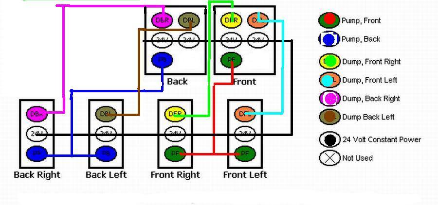
Whammy Hydraulic Wiring Diagram
Hydraulics is a topic in applied science and engineering dealing with the mechanical properties of liquids. Monarch hydraulic pump parts diagram.
Jd Hydraulics Schematic Diagram.

Whammy hydraulic wiring diagram. They are often photos attached with highly-detailed drawings or. Is the most common wiring youll see on a setupseries wiring will increase the voltage over each battery by 12v ut will maintain the amperage no matter how many batteries are wired in seriesso 6 batteries wired in series and the amps are 100 so 6 12v batteries wired in series is 72v 100. Is the least efficient diagram among the electrical wiring diagram.
Monarch master repair parts catalog for reference use only. When DigiTech Whammy is selected it is automatically placed before the Amp modeling as shown in the block diagram on page 20. Power Up Gravity Down Pump Wiring Diagram Product PM319 Pump 76630 Breaker Replacement diagram for.
Telecaster Complete CTS 250K Volume Tone Pots CRL Switch 033 Capacitor Switchcraft Output Jack Black White Vintage Cloth Wiring Kit - includes Wiring Diagram Condition. Jd Hydraulics Schematic Diagram. Pierce Stock Bed Dump.
Below are wiring diagrams for pumps used on bale spikes and dump kits. 4932730-c wiring diagram e-stop self lvl bskt 0255004-e assy eng stop ctrl bskt hydraulic 1282898-- chart hyd diagram self level 2792504b_m-- hyd diagram self lev platform 94 con rot 0257672-- inst o-l sw relocate 2791946-d chart hydraulic diagram basket level 2792501b_m-- hyd self lev platform 94 mechanical 0257673-a inst self lev platform. Hydraulic Pump Diagram Vv Schwabenschamanen De Find monarch hydraulic pump from a vast selection of parts accessories.
Oil CANNOT flow from 2 to 1. Visualizing hydraulic components in action MECHANICAL VALVES 1- CHECK VALVE NON-RETURN VALVE Oil can flow freely from 1 to 2. The difference between series wiring and parallel wiring for those who dont know.
Fluid mechanics provides the theoretical foundation for hydraulics which focuses on the engineering uses of fluid properties. Its components are shown by the pictorial to be easily identifiable. Each Preset will fall into one of three roupsWhammy Harmony or Detune.
By Svetlana Karpenko On February 26 2021 In Wiring Diagram 207 views. 10 Switch Wiring Diagram 2000 Windstar Begeboy Source. Hydraulic pump wiring diagram.
Wiring Diagram Book A1 15 B1 B2 16 18 B3 A2 B1 B3 15 Supply voltage 16 18 L M H 2 Levels B2 L1 F U 1 460 V F U 2 L2 L3 GND H1 H3 H2 H4 F U 3 X1A F U 4 F U 5 X2A R Power On Optional X1 X2115 V 230 V H1 H3 H2 H4 Optional Connection Electrostatically Shielded Transformer F U 6 OFF ON M L1 L2 1 2 STOP OL M START 3 START START FIBER OPTIC. February 25 2021 by Arie. Digitech Whammy As the Pedal is moved the note bends either up or down.
Pierce Stock Bed Dump Kits Power Up Gravity Down Pump Wiring Diagram Product. Ag agp20 agp30 att30 be s33 be s50 be s75 bt4 whb c ccy cwj. In fluid power hydraulics is used for the generation control and transmission of power.
3Ø WIRING DIAGRAMS 1Ø WIRING DIAGRAMS Diagram ER9 M 3 1 5 9 3 7 11 Low Speed High Speed U1 V1 W1 W2 U2 V2 TK TK Thermal Overloads TWO SPEED STARDELTA MOTOR Switch M 3 0-10V 20V 415V AC 4-20mA Outp uts Diagram IC2 M 1 240V AC 0-10V Outp ut Diagram IC3 M 1 0-10V 4-20mA 240V AC Outp uts These diagrams are current at the time of publication. Whammy - This group of Presets will bend your incoming signal either up or down depending pon the Preset you have chosen. Dump Trailer Pump Wiring Diagram.
UPGRADES CAN ONLY BE USED WHEN ORDERING FULL KITS. Part numbers are possibly not current. Pmax 180bar As long as P.
12 posts related to Dump Trailer Hydraulic Pump Wiring Diagram. Upgrade to 1 Whammy Tank 2 3 Pump Kit quantity. 10 switch box wiring diagram block hydraulics fuse hydrualic10 hydraulic 2 2000 windstar for switches cce f150 starter hp exstream architecture full ca 6489 ford 7810 di service diagramasde com diagramas ft flexitest type 1 800n2 800mhz signal enhancer user 4020 fuel pump 1996 toyota land cruiser electrical float installation upgrade.
At a very basic level hydraulics is the liquid version of pneumatics. Home Hydraulic Kit Upgrades Hijacker Hydraulic Kit Upgrades Upgrade to 1 Whammy Tank 2 3 Pump Kit Upgrade to 1 Whammy Tank 2 3 Pump Kit 7500. Lippert Hydraulic 19832 Wiring Diagram It is far more helpful as a reference guide if anyone wants to know about the homes electrical system.
Dump Trailer Hydraulic Pump Wiring Diagram. 12v Hydraulic Pump Wiring Diagram. Diagram Wiring Box Switch Hydraulic 10pdf s elite Lowell High School would permanently switch to lottery admission under fast-track proposal That vote garnered national headlines and sparked a brutal division in the city over the timing with many parents criticizing the move as a distraction from reopening schools after 10 months of distance learning.
Page 9 ED will light to indicate which preset has been selected. Home Diagrams Dump Trailer Hydraulic Pump Wiring Diagram. Connect the power supply between an AC outlet and the power jack on the Whammy.
2- PRESSURE RELIEF VALVE Is used to set the maximum working pressure of the hydraulic system and therefore the capacity of the lift. PM319 Pump PS025 Safety Cut-off Switch Replacement diagram for.
 Hitachi Ex55ur Hydraulic Circuit Diagram Circuit Diagram Diagram Diagram Online
 Western Joystick Controller Wiring Diagram Dump Trailers Trailer Wiring Diagram Hydraulic Pump
 How To Analyze And Troubleshoot Hydraulic Circuit Problems Youtube Hydraulic Systems Mechanical Engineering Engineering
 Animation How Basic Hydraulic Circuit Works Technical Video Hydraulic Circuit


